What is a SWR?

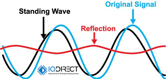
SWR (Standing Wave Ratio) - in RF engineering and microwave, the ratio of the amplitude of the maximum (in a line) to the amplitude of the minimum (in the same line) of the standing wave in a cable, antenna or waveguide. SWR is a rate of the impedance matching of the load with the internal impedance of the feeder line or waveguide. The problem with mismatched impedance leads to the appearance of unwanted standing waves along the transmission line.
SWR is defined as the ratio of the amplitude of the standing wave (unwanted) in the maximum to the amplitude at the minimum along the transmission line. SWR characterizes the degree of matching of the loading Wi-Fi antenna and the feeder (coaxial cable or feeding waveguide). Sometimes SWR is given for matching the output of the wireless Wi-Fi Access point and it’s feeder.
In practice, there always exists some part of the transmitted energy that is reflected and returned back to the transmitter. Too much reflected energy degrades the operation of the wireless transmitter or can even damage it.
Typically, the SWR is perceived from the point of view of the maximum and minimum alternating voltage along the coaxial line, which is called the ratio of the standing voltage wave or VSWR. For example, the value of the VSWR 1.2: 1 means the RF voltage due to standing waves along the transmission line, reaching a peak value of 1.2 times greater than the minimum RF voltage along this cable. The SWR can also be defined as the ratio of the maximal amplitude to the minimal amplitude of the electric field strength, magnetic field strength or currents of the power line. These relationships could be identical If we are neglecting the loss of the transmission line itself.
Ideally, the SWR = 1 - this means that the reflected wave is absent. Values up to 1.5 are considered acceptable in the Wi-Fi range of 2400-2485 MHz.
When a reflected wave appears, the SWR increases in direct proportion to the degree of feeder and load mismatch. In practice, the Voltage Standing Wave Ratio (VSWR) is more often used. This parameter must be specified in the technical requirements for the transmitting device. In addition, there are standards for the maximum permissible level of SWR.
The SWR is the inverse of the traveling wave ratio (TWR).
With poor load match, standing waves appear in the cable, which worsen the work of Wi-Fi equipment as a result of:
- reduces the efficiency of the feeder, and, therefore, the overall efficiency of the transmitter; the real sensitivity of the receiver decreases;
- reduces maximum power that can be brought to the antenna-feeder device;
- matching of the transmitter and receiver with the antenna-feeder device is difficult.
But, it can be concluded that the existing antenna-feeder device will work much better if the SWR is reduced to 1 only after comparing its characteristics with the existing equipment with SWR and SWR = 1.
To measure the standing wave ratio, special measuring instruments called the SWR-meters are used. Since the SWR is a coefficient of the load impedance relative to the characteristic impedance of the transmission line used (which together determines the reflection coefficient), this SWR meter can only interpret the impedance that it sees in terms of SWR if it was designed for this specific impedance. In practice, most of the transmission lines used in modern applications are coaxial cables with a resistance of 50 or 75 Ohms, so most SWRs correspond to one of them.

